![]() Create Shark Mesh
Create Shark Mesh
![]()
![]()
![]()
![]()
![]()
![]()
![]()
![]()
![]()
![]()
|
|
|
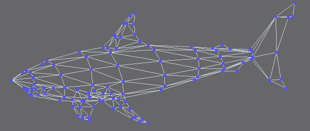
First we need to review the terminology used in gmax. An Editable Mesh is a set of triangles that define the surface of an object in 3D space. At the lowest level, we have vertices, which are just 3D coordinates. An edge connects two vertices. A face is a triangle that contains three edges and three vertices. A polygon usually contains more than 3 edges. Polygons are usually shown in viewports as quadrilaterals, with a hidden edge dividing each quad into triangles. An element is a subset of faces in an editable mesh. An element is created when you attach one mesh to another. You can also designate arbitrary faces as belonging to a particular element at any time. Let's take some time to consider other constraints imposed by There on our hoverboard model. The hoverboard template html document lists the following constraints:
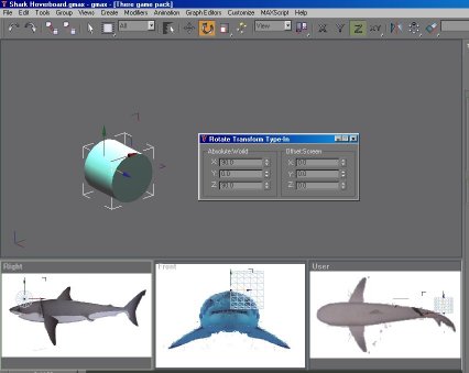
Notice that the document incorrectly lists LOD1 polygon count as 116. I have confirmed with There that it should be 160. Also when There folks talks about polygons, they mean "gmax faces". Gmax itself also uses the word "polygon" in place of "faces" in many places. We will start building the shark model in LOD0 which has the most vertices and polygons. After the model is done in LOD0, we will reduce vertices and polygons to meet requirements for LOD1 and LOD2. While in theory we can start with as many vertices and polygons as we like, then use the Mesh Optimize modifier in gmax to quickly reduce polygons, I have found the result of such optimization unsatisfactory. Mesh Optimize may work magic, if you are reducing 5,000 thousand polygons down to 1,000 polygons. When we are talking about a mere 170 vertices and 160 polygons for LOD1, such automatic optimization almost always reduce polygons at the wrong places. Why I am so obsessed with LOD1? Well, you will be lucky if you actually see your LOD0 model used in There for more than a dozen seconds a day. When you first take out your hoverboard, for a few brief seconds, you will be looking at a big, detailed board. That is LOD0 right there. But as soon as you jump onto it, you'll be using the LOD1 model. Also, most other people around you aren't usually close enough to your shark to appreciate its LOD0 model. They usually see you in LOD1 model, as you cruise around. So, I recommend that you start with about the right amount of polygons. In general, use less vertices in flat areas early during modeling. This will save you a lot of optimization time later. Trust me, I learned it the hard way with my dolphin model. It is now time to hide all objects in your scene, so we can create the embryonic body of our shark.
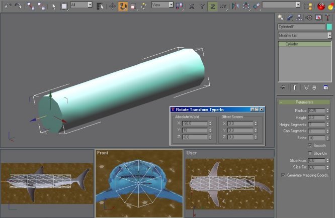
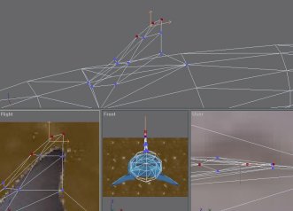
I just realized that I should have given a background color to these background images, so that the cylinder mesh stand out clearly from the background. Bring up these images in PSP and add a background layer (I told you lazy guys to save your pictures in .psp earlier, remember?)
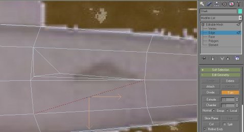
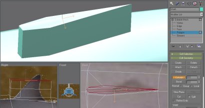
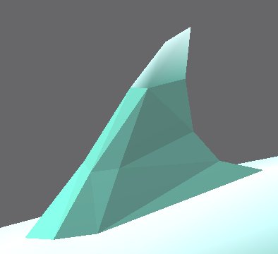
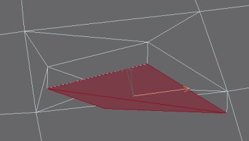
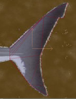
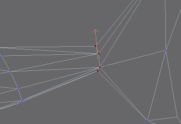
Select the 4 polygons that form the base, and extrude them twice. I usually don't bother with extrude value and bevel value. Once you have the extra extruded faces, you can go to the Vertex SubObject mode to move and scale these vertices to fit the dorsal find background. Once you have adjusted these vertices, you can Collapse the three vertices at the top of the fin which are very close to one another. Finally, select the middle edge of the top of the fin, and Divide it twice to create the last two top-most vertices.
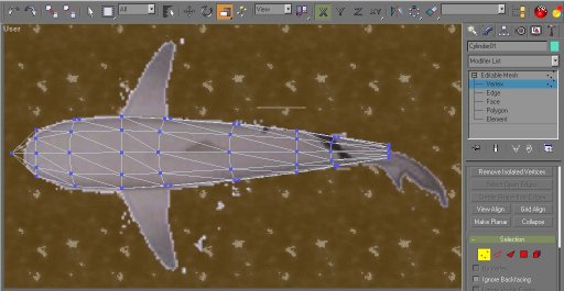
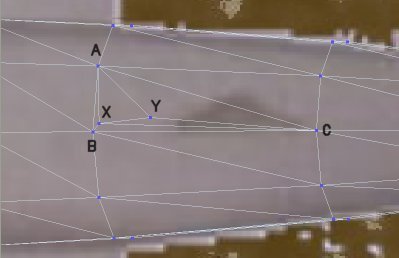
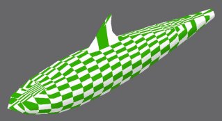
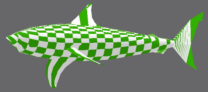
Also split the edge at the back of the fin to create a smoother back curve. Use Edge Turn to adjust the surface to make the fin look more natural. Make a few final adjustments to vertices at the base of the fin, and we are done with the dorsal fine! In the material navigator, create a new Checker texture to show curves in the model more clearly. If you can't get the checker pattern to show up, then you probably did not enable Generate Texture Coords when you created the cylinder. You can add a "UVW Map" modifier to the editable mesh. Choose cylinder mapping. You can then collapse this modifier onto the mesh. We will later override this temporary map, when the shark is fully modeled.
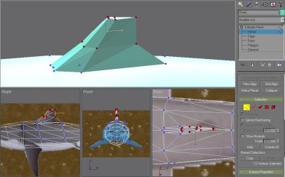
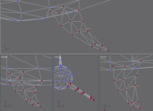
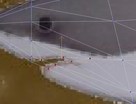
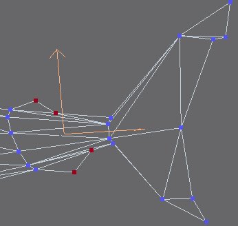
To create the pectoral fins, we first create the outline of the base of the left pectoral fin. Use Face Divide to create the three vertices indicated in the picture. You may need to do an Edge Turn to correct automatically created edges. Now extrude the two faces enclosed by the 4 base vertices, and move the newly created faces out. Then move vertices of these new faces to fit the background pictures. Extrude one more time and adjust vertices. Finally divide the edge at the tip of the fin twice to create two vertices and move them to finish modeling the fin. You may have noticed that we have not followed the background pictures strictly. We have lifted the fins a bit to avoid sinking pectoral fins into the ground, when the shark hoverboard is used in-world.
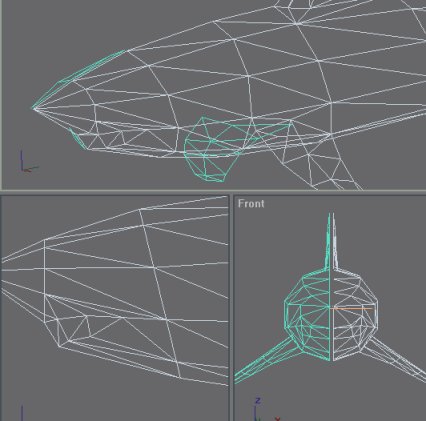
We could have done this earlier, but it is not too late to do it now. Let's remove the right half of the shark, so we can create a mirror image to save ourselves some valuable time. I am sure you have followed the gmax tutorial "Modeling a Head", so you should be quite familiar with this exercise. We'll select all faces on the right side and simply delete them. Select the editable mesh (quit the SubObject selection mode), and click on the Select and Mirror button. Mirror along the X axis and check Clone Instance. Enter a mirror offset of -0.02 to create a visual gap between the two parts.
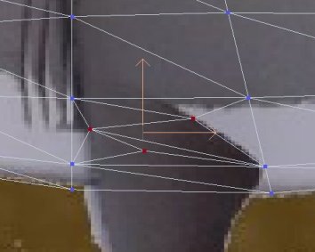
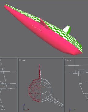
To create the mouth, we first use Edge Cut to cut out the basic outline of the mouth. This creates 6 extra vertices. Select the 3 vertices in the lower jaw and move it in the side viewport to create a more menacing jaw. I would love to model the mouth cavity and the full set of teeth. But keep The all-important Constraints in mind; we can't afford to do that. I think we'll have to content ourselves with painted teeth.
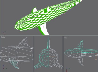
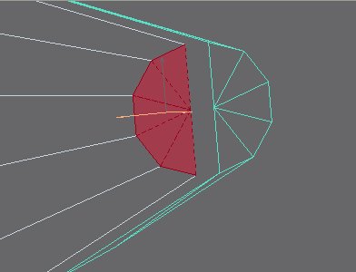
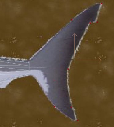
While our shark has a pair of pelvic fins, an anal fin and a second smaller dorsal fin in real life, we may not be able to model these. We have already created 284 polygons (actually faces) so far. Clearly we will need to do some reduction if we want to accommodate the full set of fins. We will see how many polygons we waste creating the caudal fin (the tail). We first remove unneeded polygons from the cap of the cylinder. We have saved 10 polygons for the time being. In the side viewport, using vertex SubObject selection model, create a set of vertices to trace the outline of the fin. Create a polygon by clicking on each vertex around the outline of the fin in counterclockwise order. If the normals are inverted (e.g. you created the polygon in clockwise order), you can always invert it in the Modifier panel's Surface Properties rollout. Finally, we collapse two pairs of vertices between the body and the fin to reduce polygons.
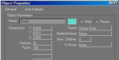
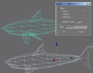
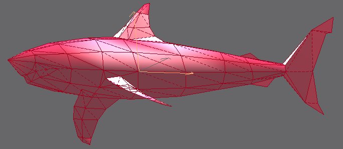
Before we merge the two halves of the shark, we should save the original half, in case we need it. We may also use it to create LOD1 and LOD2, instead of starting from the final LOD0 shark. Make a so-called shift-copy. Click on Select and Move, then move the shark away while holding down the shift key. Choose 'copy' and name the new object 'Shark Half'. Then hide this new object. Once this is done, delete the mirror instance and re-create a mirror 'copy' with x-offset of 0. Attach the mesh copy to the original half. Make sure you weld all vertices that lie on the y-z plane. Procedures for doing this is covered in details in the Modeling a Head tutorial. Notice that the scale of objects in the tutorial is very different from the hoverboard model. You need to use a very small number such as 0.001 to weld the vertices. Before the weld operation, we have 188 vertices. After the operation, we have 152 vertices. Our current vertex/polygon counts satisfy the constraints for LOD0. That is very good. Ah, we can now proceed to Create Texture Map for the shark
|